I want to use MC-WP7607 with my board. at the moment, I check pinning of module to validate my uses cases. There is some misunderstanding on WP76xx MiniCard Accessory Board - Product Technical Specification. On pinnout section, I don’t understand the WP gpio association of mpci express pin :
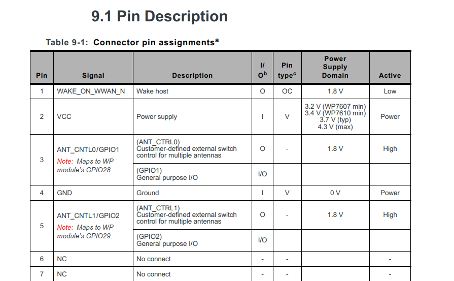
pin 3 -> GPIO 1 or GPIO 28
pin 5 -> GPIO 2 or GPIO 29
pin 44 -> GPIO 3 or GPIO 30
pin 46 -> GPIO 21 or GPIO 31
More over, on Figure 2-1 Accessory Board Architecture Overview, there is reset signal between PCIE interface and WP module. on the pinout section, pin 33 seems to link with RESET but it’s marked as NC on signal column. Can I use pin 33 to do electric reset ? Pin 33 is it link to RESET_IN_N signal of WP module ?
Can you clarify the pinout please ?
I don’t find schematic resource on your site. Where can I find it ?
Customer-defined external switch control for multiple antennas.
These pins can be configured for use as GPIOs using +WIOCFG
GPIO Configuration (+WIOCFG)
Configure a specific GPIO (I/O port) for one of the following uses (indicated by the
parameter): • GPIO, accessible via AT commands ( = 4) • Usage by the embedded Linux host ( = 16) • Deallocate port ( = 0) • Antenna select using GPIOs 28–31 ( = 0, then !ANTSEL can be used)
5.4 Tx Power Control
GPIO control via !SARGPIO command (see [1] AirPrime WP8548/WP75xx/
WP76xx/WP77xx AT Command Reference)—Set an unallocated external GPIO
to control SAR. (Available GPIOs are ANT_CNTL0:2 (correspond to WP76xx
GPIO28–30) and GPIO21.)
5.7 General Purpose Input/Output (GPIO)
The AirPrime WP76xx Accessory Board defines several GPIOs for customer use, as
described
Pin numbers 3, 5, and 44 map to the WP module’s GPIO28, GPIO29, and
GPIO30, respectively. References to GPIOs in [1] AirPrime WP8548/WP75xx/WP76xx/
WP77xx AT Command Reference use the WP module pin identifications.
The AirPrime WP76xx Accessory Board provides three output signals that can be
used for host designs that incorporate tunable antennas
5.12 Antenna Control
The AirPrime WP76xx Accessory Board provides three output signals that can be
used for host designs that incorporate tunable antennas.
Signal direction with respect to module.
Examples: ANT_CNTL0 (pin 153 ) is an output from the module to the host
Configure a specific GPIO (I/O port) for one of the following uses (indicated by the
parameter): • GPIO, accessible via AT commands ( = 4) • Usage by the embedded Linux host ( = 16) • Deallocate port ( = 0) • ANT_CNTL0 - ANT_CNTL2, GPIO21 is set by AT!ANTSEL using GPIO_28 to GPIO_31 respectively
I understand that AT command WIOCFG allow to select alternate function of one GPIO. I understand that if I want to selection antenna I must to deallocate port of GPIO 28-31. For instance, If I want to use one GPIO by the embedded Host for toggle one externally LED via pin 46 of mPci express connector. What is it the GPIO that I must configure with AT command WIOCFG ? (GPIO 21 or GPIO 31)